Burkert Type 8605 User Manual
Browse online or download User Manual for Accessories for water Burkert Type 8605. Burkert Type 8605 User Manual
- Page / 108
- Table of contents
- BOOKMARKS
- Operating Instructions 1
- Type 8605 1
- Contents 3
- 1. OPERATING INSTRUCTIONS 5
- 2. INTENDED USE 6
- 3. BASIC SAFETY INSTRUCTIONS 7
- 4. GENERAL INFORMATION 8
- 5. PRODUCT DESCRIPTION 9
- Product description 10
- 6. TECHNICAL DATA 11
- 7.1.1. Operating unit 12
- 7.2. Basic function 13
- 2 % 100 % 15
- 8. INSTALLATION 16
- Installation 17
- 8.2.2. DIN rail version 18
- 9. CONFIGURATION 20
- Configuration 21
- CAUTION! 23
- Figure 26: dAtA (Data) 30
- 11. SPARE PARTS 33
- 11.2. Accessories 34
- 12. PACKAGING, TRANSPORT 35
- 13. STORAGE 35
- 14. DISPOSAL 36
- Typ 8605 37
- 1. DIE BEDIENUNGSANLEITUNG 39
- Bestimmungsgemäße Verwendung 40
- HINWEIS! 41
- 4. ALLGEMEINE HINWEISE 42
- 5. SYSTEMBESCHREIBUNG 43
- Systembeschreibung 44
- 6. TECHNISCHE DATEN 45
- 7. AUFBAU UND FUNKTION 46
- 7.2. Grundfunktion 47
- 8. MONTAGE 50
- 8.2.2. Hutschienenausführung 52
- 9. KONFIGURATION 54
- Konfiguration 55
- VORSICHT! 57
- Grundgerät 64
- 10. WARTUNG 66
- 11. ERSATZTEILE 67
- 11.2. Zubehör 68
- 12. VERPACKUNG, TRANSPORT 69
- 13. LAGERUNG 69
- 14. ENTSORGUNG 70
- AVERTISSEMENT ! 73
- DANGER ! 73
- ATTENTION ! 73
- REMARQUE ! 73
- 2. UTILISATION CONFORME 74
- 3. CONSIGNES DE SÉCURITÉ 75
- FONDAMENTALES 75
- REMARQUE! 76
- 4. INDICATIONS GÉNÉRALES 77
- 5. DESCRIPTION DU SYSTÈME 78
- Description du système 79
- 7. STRUCTURE ET FONCTIONS 81
- 7.2. Fonctionnement de base 82
- ATTENTION! 92
- Figure 26 : dAtA (Data) 99
- 9.3.11. END 100
- 10. MAINTENANCE 101
- 11. ACCESSOIRES 102
- 11.2. Accessoires 103
- 12. EMBALLAGE, TRANSPORT 104
- 13. STOCKAGE 104
- 14. ELIMINATION 105
Summary of Contents
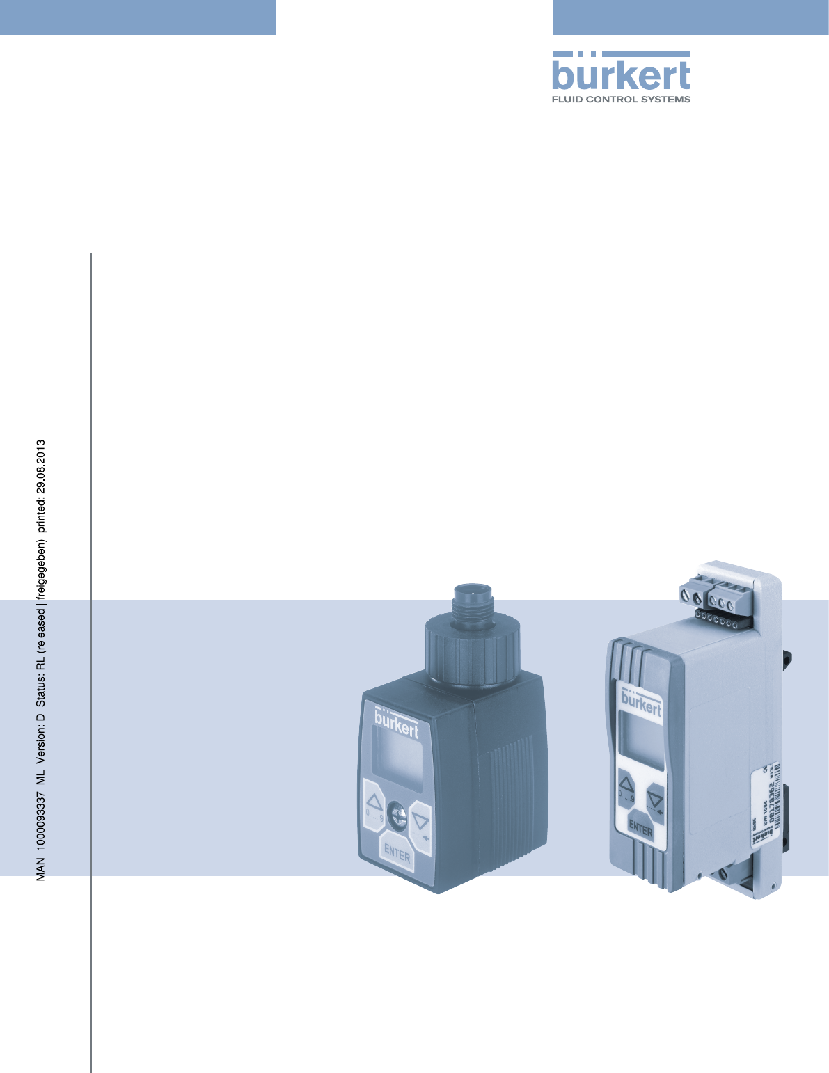
Operating InstructionsBedienungsanleitung Manuel d‘utilisationType 8605 Digital Control Electronics for Proportional ValvesDigitale Ansteuerelektronik
10Product descriptionPlug-in version on valves with connector pattern A: e. g. types 2832, 2833, 2834, 2835, 2836, 2853, 2863, 2865, 2873, 2875
100ConfigurationdnLd (download) Lors de le «download» les paramètres enregistrée dans la mémoire de l‘unité de commande sont transmis à l‘appareil de
101Maintenance10. MAINTENANCE10.1. Consignes de sécuritéAVERTISSEMENT!Risque de blessures dû à des travaux de maintenance non conformes !• La maint
102Accessoires11. ACCESSOIRESATTENTION!Risque induit par l’utilisation d’accessoires et de pièces de rechange inadaptés!L’utilisation d’accessoires o
103AccessoiresS’il y en a deux possibilités de valeur du courent, choise le petit.11.2. AccessoiresAccessoires / Éléments N° d'identificationUni
104Emballage, transport12. EMBALLAGE, TRANSPORTREMARQUE! Dommages dus au transport !Les appareils insuffisamment protégés peuvent être endommagés pen
105Elimination14. ELIMINATION → Eliminez l’appareil et l’emballage dans le respect de l’environnement.REMARQUE ! Dommages à l’environnement causés pa
106 Type 8605français
www.burkert.com
11Technical Data6. TECHNICAL DATA6.1. Operating ConditionsWARNING!The Type 8605 is not designed for use outdoors!• Do not use the Type 8605 outdoor
12Configuration and Function7. CONFIGURATION AND FUNCTION7.1. Operating and Display Elements7.1.1. Operating unitThe operating unit consists of a L
13Configuration and Function7.1.2. LED’s during operation without operating unitDuring operation of the Control Electronics 8605 without operating un
14Configuration and FunctionDue to the inductivity of the coil, the rectangular time curve of the PWM voltage signals is not transformed into a corres
15Configuration and FunctionI2I1I2 % 100 %Standard signalFigure 7: Current over standard signalThe working range can also be scaled using the key va
16Installation8. INSTALLATION8.1. Safety instructionsDANGER!Risk of injury from high pressure in the equipment!• Before loosening the lines and val
17Installation12 . 24 V DCGNDStandard signal (-)Standard signal (+)Figure 9: Terminal strip connection12 . 24 V DCGNDStandard signal (-)Standard sign
18InstallationTighten screw M3 to max. 0.3 NmFigure 11: Installation of the cable plug version on the valve8.2.2. DIN rail versionThe electrical con
19Installation176523498Figure 12: Terminal strip connectionLegend:1. 12 ... 24V DC2. GND3. Standard signal (-)4. Standard signal (+)5. Valve6.
We reserve the right to make technical changes without notice.Technische Änderungen vorbehalten.Sous réserve de modifications techniques.© 2007 - 2012
20Configuration9. CONFIGURATIONWARNING!Danger may result from improper use!Improper use can result in personal injury or damage to the device.• The
21ConfigurationA sub-menu appears on the display. You can switch between the sub-menu items by pressing the arrow keys and make the desired settings.
22Configuration9.3.1. InP (Input) - Selection of the input signalEnter the type of standard signal used in this menu item. You can select between the
23ConfigurationFigure 16: Out (output) - Valve settingVALV (VALVE) - SETTING OF THE VALVE TYPECAUTION!Danger from the selection of the wrong valve ty
24Configuration0 %τ60 %100 %fLOffHIFigure 17: PWM frequency / pulse duty factorThe two limit frequencies of the PWM control (HI and LO) are set with
25ConfigurationCAUTION!Danger from wrong setting of the valve type.If the selected valve type differs from the valve actually used whose coil has very
26Configuration• The following rule applies for the input of the frequency pairs: HI value > LO value• In the menu item VALV, the HI and LO value
27Configuration → Start with a current value at which the valve is still reliably closed and increase the coil current with the arrow key until the
28ConfigurationFigure 21: dELY (Delay) - Ramp function9.3.6. Cut (Cut off) - Zero point cut offIn order to guarantee leak-tight closing of the valve
29Configuration9.3.7. PArA (Parameter) - Controller settingThe controlled coil current cannot follow changes in the input signal at any random speed.
3 Contents1. OPERATING INSTRUCTIONS ...
30Configuration9.3.9. SPOS (Safe position) - Setting of the safety positionInput of the safety position (0.0 to 100.0 %) that is controlled with a se
31ConfigurationdnLd (download) When download is selected the parameters stored in the operating unit are transferred to the basic devi
32Maintenance10. MAINTENANCE10.1. Safety InstructionsWARNING!Danger due to improper maintenance work!Improper maintenance may result in injuries as
33Spare Parts11. SPARE PARTSCAUTION!Danger due to incorrect accessories and replacement parts!Incorrect accessories or unsuitable spare parts can res
34Spare PartsIf two current ranges of the control electronics are possible choose the lower one11.2. AccessoriesAccessories / Individual parts Identi
35Packaging, Transport12. PACKAGING, TRANSPORTNOTE! Transport damages!Inadequately protected equipment may be damaged during transport.• During tran
36Packaging, Transport14. DISPOSAL → Dispose of the device and packaging in an environmentally friendly manner.NOTE! Damage to the environment caused
37 Inhalt1. DIE BEDIENUNGSANLEITUNG ...
38 8.2.1. Elektrischer Anschluss der Gerätesteckdose ...508.2.2. Huts
39Die Bedienungsanleitung1. DIE BEDIENUNGSANLEITUNGDie Bedienungsanleitung beschreibt den gesamten Lebenszyklus des Gerätes. Bewahren Sie diese Anlei
4 8.2.1. Cable plug version ...
40Bestimmungsgemäße Verwendung2. BESTIMMUNGSGEMÄSSE VERWENDUNGBei nicht bestimmungsgemäßem Einsatz der Digitalen Ansteuerelektronik für Proportionalv
41Grundlegende Sicherheitshinweise3. GRUNDLEGENDE SICHERHEITSHINWEISEDiese Sicherheitshinweise berücksichtigen keine:• Zufälligkeiten und Ereignisse
42Allgemeine Hinweise4. ALLGEMEINE HINWEISE4.1. KontaktadresseDeutschlandBürkert Fluid Control Systems Sales Center Christian-Bürkert-Str. 13-17 D-7
43Systembeschreibung5. SYSTEMBESCHREIBUNG5.1. Vorgesehener EinsatzbereichDer Typ 8605 ist für den dauerhaften Einsatz in Industrieumgebung konzipier
44SystembeschreibungAufsteckbare Version auf Ventile mit Steckerbild A: z. B. die Typen 2832, 2833, 2834, 2835, 2836, 2853, 2863, 2865, 2873, 287
45Technische Daten6. TECHNISCHE DATEN6.1. BetriebsbedingungenWARNUNG!Verletzungsgefahr!Funktionsausfall bei Einsatz im Außenbereich!• Typ 8605 nich
46Aufbau und Funktion7. AUFBAU UND FUNKTION7.1. Bedien- und Anzeigeelemente7.1.1. BedieneinheitDie Bedieneinheit besteht aus LCD-Display und Tasten
47Aufbau und Funktion7.1.2. LEDs bei Betrieb ohne BedieneinheitBei Betrieb der Ansteuerelektronik 8605 ohne Bedieneinheit wird der Betriebszustand du
48Aufbau und FunktionDer rechteckige Zeitverlauf des PWM-Spannungssignals wird wegen der Induktivität der Spule nicht in einen ent-sprechenden Stromve
49Aufbau und FunktionI2I1I2 % 100 %NormsignalBild 7: Strom über NormsignalMit den Eckwerten I1 bzw. I2 kann der Arbeitsbereich auch so skaliert werd
5Operating Instructions1. OPERATING INSTRUCTIONSThe operating instructions describe the entire life cycle of the device. Keep these instructions in a
50Montage8. MONTAGE8.1. SicherheitshinweiseGEFAHR!Verletzungsgefahr durch hohen Druck in der Anlage!• Vor dem Lösen von Leitungen und Ventilen den
51Montage12 . 24 V DCGNDNormsignal (-)Normsignal (+)Bild 9: Anschluss Klemmleiste12 . 24 V DCGNDNormsignal (-)Normsignal (+)Bild 10: Anschluss Steck
52MontageSchraube M3 mit max. 0,3 Nm anziehenBild 11: Montage der Gerätesteckdoseausführung an das Ventil8.2.2. HutschienenausführungDer elektrische
53Montage176523498Bild 12: Anschluss KlemmleisteLegende:1. 12 ... 24 V DC2. GND3. Normsignal (-)4. Normsignal (+)5. Ventil6. Ventil7. RS485-B7
54Konfiguration9. KONFIGURATIONWARNUNG!Gefahr durch unsachgemäßen Betrieb!Unsachgemäße Bedienung kann zu Personenschäden oder Schäden am Gerät führen
55KonfigurationAuf dem Display erscheint ein Untermenü. Durch Betätigen der Pfeiltasten können Sie zwischen den Untermenüpunkten wechseln und die gewü
56Konfiguration9.3.1. InP (Input) - Auswahl des EingangssignalGeben Sie unter diesem Menüpunkt die Art des verwendeten Normsignals an. Sie können zwi
57KonfigurationBild 16: Out (Output) - VentileinstellungenVALV (VALVE) - EINSTELLUNG DES VENTILTYPSVORSICHT!Gefahr durch die Auswahl des falschen Ven
58Konfiguration0 %τ60 %100 %fLOffHIBild 17: PWM-Frequenz / TastverhältnisMit der Auswahl des Ventiltyps werden die beiden Grenzfrequenzen der PWM-An
59KonfigurationVORSICHT!Gefahr durch falsche Angabe des Ventiltyps!Wenn statt tatsächlich verwendeten Ventils ein abweichender Typ angewählt wird, des
6Intended Use2. INTENDED USENon-intended use of the Type 8605 may be a hazard to people, nearby equipment and the environment. • The device is desig
60Konfiguration9.3.4. AdJ (Adjust) - Anpassung des SpulenstromsDer Arbeitsbereich eines Proportionalventils wird durch den Spulenstrom definiert. •
61KonfigurationMaximaler Durchfluss → Stellen Sie den maximalen Spulenstrom I2 (AdJ = HI mA) über die Pfeiltasten so ein, dass gerade der maximale Dur
62KonfigurationBild 21: dELY (Delay) - Rampenfunktion9.3.6. Cut (Cut off) - NullpunktabschaltungUm ein Dichtschließen des Ventils zu garantieren, wi
63Konfiguration9.3.7. PArA (Parameter) - ReglereinstellungDer geregelte Spulenstrom kann Änderungen des Eingangssignals nicht beliebig schnell folgen
64Konfiguration9.3.9. SPOS (Safe Position) - Einstellen der SicherheitsstellungEingabe der Sicherheitsstellung (0,0 ... 100,0 %), die bei ausgewählte
65KonfigurationdnLd (download) Beim Download werden die Geräteeinstellungen, die in der Bedieneinheit gespeichert sind, an das Grundgerät übertragen.
66Wartung10. WARTUNG10.1. SicherheitshinweiseWARNUNG!Verletzungsgefahr bei unsachgemäßen Wartungsarbeiten!• Die Wartung darf nur autorisiertes Fach
67Ersatzteile11. ERSATZTEILEVORSICHT!Verletzungsgefahr, Sachschäden durch falsche Teile!Falsches Zubehör und ungeeignete Ersatzteile können Verletzun
68ErsatzteileBei zwei möglichen Strombereichen der Ansteuerelektronik sollte die kleinere bevorzugt werden.11.2. ZubehörZubehör/Einzelteil Ident.-Nr.
69Verpackung, Transport12. VERPACKUNG, TRANSPORTHINWEIS! Transportschäden!Unzureichend geschützte Geräte können durch den Transport beschädigt werden
7Basic Safety Instructions3. BASIC SAFETY INSTRUCTIONSThese safety instructions do not make allowance for any: • Contingencies and events which may
70Verpackung, Transport14. ENTSORGUNG → Entsorgen Sie das Gerät und die Verpackung umweltgerecht.HINWEIS! Umweltschäden durch von Medien kontaminiert
71 sommaIre1. LES INSTRUCTIONS DE SERVICE ...
72 8.2.1. Exécution le connecteur ...
73Les instructions de service1. LES INSTRUCTIONS DE SERVICELes instructions de service décrivent le cycle de vie complet de l‘appareil. Conservez ces
74Utilisation conforme2. UTILISATION CONFORMEL’utilisation non conforme du type 8605 peut présenter des dangers pour les personnes, les installa-tion
75Consignes de sécurité fondamentales3. CONSIGNES DE SÉCURITÉ FONDAMENTALESCes consignes de sécurité ne tiennent pas compte :• Des hasards et des év
76Consignes de sécurité fondamentalesREMARQUE! Eléments/sous-groupes sujets aux risques électrostatiques !• L’appareil contient des éléments électron
77Indications générales4. INDICATIONS GÉNÉRALES4.1. AdressesAllemagneBürkert Fluid Control Systems Sales Center Chr.-Bürkert-Str. 13-17 D-74653 Inge
78Description du système5. DESCRIPTION DU SYSTÈME5.1. Domaine d’utilisationLe régulateur électronique de type 8605 est conçu pour une utilisation du
79Description du systèmeExécution enfichable sur vannes avec schéma de connexion A : par ex. types 2832, 2833, 2834, 2835, 2836, 2853, 2863, 2865, 2
8General Information4. GENERAL INFORMATION4.1. Contact addressGermanyBürkert Fluid Control Systems Sales Center Chr.-Bürkert-Str. 13-17 D-74653 Inge
80Caractéristiques techniques6. CARACTÉRISTIQUES TECHNIQUES6.1. Conditions d‘exploitationATTENTION !Risque de blessures !Panne en cas d’utilisation
81Structure et fonctions7. STRUCTURE ET FONCTIONS7.1. Éléments de commande et d’affichage7.1.1. Unité de commandeL’unité de commande se compose d’u
82Structure et fonctions7.1.2. DEL pour les exécutions sans unité de commandeDans le cas de l’utilisation du régulateur électronique 8605 sans unité
83Structure et fonctionsLe tracé chronologique rectangulaire du signal de tension MLI ne se traduit pas par un tracé de courant corres-pondant en rais
84Structure et fonctionsI2I1I2 % 100 %Signal normaliséFigure 7 : Rapport entre courant et signal normaliséAvec les paramètres fondamentaux I1 et I2,
85Montage8. MONTAGE8.1. Consignes de sécuritéDANGER!Danger dû à la haute pression !• Avant de desserrer les conduites et les vannes, coupez la pres
86Montage12 . 24 V DCGNDSignal normalisé (-)Signal normalisé (+)Figure 9 : Raccordement sur la borne plate12 . 24 V DCGNDSignal normalisé (-)Signal n
87MontageSerrer la vis M3 avec 0,3 Nm maximum.Figure 11 : Montage de l’exécution connecteur sur la vanne8.2.2. Exécution profilé chapeauLe brancheme
88Montage176523498Figure 12 : Raccordement sur la borne plateLégende:1. 12 ... 24 V DC2. GND3. Signal normalisé (-)4. Signal normalisé (+)5. Van
89Configuration9. CONFIGURATIONAVERTISSEMENT!Risques induits par une utilisation non conforme!Une utilisation non conforme peut provoquer des dommage
9Product description5. PRODUCT DESCRIPTION5.1. Field of ApplicationThe Control Electronics, Type 8605, is designed for continuous operation in indus
90ConfigurationUn sous-menu apparaît à l’écran. Les touches fléchées permettent de naviguer entre les fonctions des sous- menus et d’effectuer les rég
91Configuration9.3.1. InP (Input) - Sélection du signal d’entréeCette fonction du menu sert à indiquer la nature du signal normalisé utilisé. Il est
92ConfigurationFigure 16 : Out (Output) - Réglages de la vanneVALV (VALVE) - RÉGLAGE DU TYPE DE VANNEATTENTION!Risque induit par la sélection d’un ty
93Configuration0 %τ60 %100 %fLOffHIFigure 17 : Fréquence MLI/Durée relative des impulsionsLes deux fréquences limites de la régulation MLI (HI et LO)
94ConfigurationATTENTION!Risque induit par l’indication incorrecte du type de vanne.Si un type différent de celui de la vanne effectivement utilisée e
95Configuration9.3.4. AdJ (Adjust) - Adjustment du courant de bobineLa plage de travail d’une vanne proportionnelle est définie par le courant de bob
96ConfigurationDébit maximal → Régler le courant de bobine maximal I2 (AdJ = HI mA) à l’aide des touches fléchées, de manière à atteindre précisément
97ConfigurationFigure 21 : dELY (Delay) - Fonction de rampe9.3.6. Cut (Cutt off) - Déclenchement du point zéroAfin de garantir une fermeture herméti
98Configuration9.3.7. PArA (Parameter) - Réglage du régulateurLe courant de bobine réglé ne peut pas suivre à volonté les variations rapides du signa
99Configuration9.3.9. SPOS (Safe position) - Réglage de la position de sécuritéIndication de la position de sécurité (0,0 ... 100,0 %), réglée en cas
More documents for Accessories for water Burkert Type 8605


Related products and manuals for Accessories for water Burkert Type 8605
 (102 pages)
 (102 pages)
 (102 pages)
 (16 pages)
© 2020, manymanuals.com. All rights reserved. | 1.663 s |
 Manymanuals.com
 Manymanuals.de
 Manymanuals.fr
 Manymanuals.it
 Manymanuals.pl
 Manymanuals.cz
 Manymanuals.es
 Manymanuals-pt.com
Comments to this Manuals