Burkert Type 3004 User Manual
Browse online or download User Manual for Accessories for water Burkert Type 3004. Burkert Type 3004 User Manual
- Page / 62
- Table of contents
- BOOKMARKS
- Quickstart 1
- Type 3004 1
- LCIE 07 ATEX 6078 X 1
- Contents: 3
- 1. QUICKSTART 4
- 2. CORRECT USE 5
- 4. GENERAL INFORMATION 6
- 5. SYSTEM DESCRIPTION 7
- 6. TECHNICAL DATA 8
- 7. INSTALLATION 10
- (actuators 100 - 300 Nm) 11
- 8. INSTALLATION 12
- Fig. 17: Circuit diagram 15
- 8.3. Control card 16
- OFF (turned off) 17
- ON (turned on) 17
- 9. START-UP 19
- 10.1. Malfunctions 20
- 12. DER QUICKSTART 22
- 13. BESTIMMUNGSGEMÄSSE 23
- VERWENDUNG 23
- 14. GRUNDLEGENDE 23
- SICHERHEITSHINWEISE 23
- 15. ALLGEMEINE HINWEISE 24
- 16. SYSTEMBESCHREIBUNG 25
- 17. TECHNISCHE DATEN 26
- II 2 G D 27
- 18. MONTAGE 28
- Bild 6: Standardinstallation 29
- 19. INSTALLATION 31
- Standardausführung 32
- Bild 14: Drei Punkt Modus 33
- 19.3. Regelkarte 35
- 19.3.2. Parameter einstellen 36
- 19.3.3. Normalbetrieb 38
- 20. INBETRIEBNAHME 39
- 21. WARTUNG, FEHLERBEHEBUNG 39
- → Stromzufuhr überprüfen 40
- 23. QUICKSTART 42
- 24. UTILISATION CONFORME 43
- 25. CONSIGNES DE SÉCURITÉ 43
- FONDAMENTALES 43
- 26. INDICATIONS GÉNÉRALES 44
- 27. DESCRIPTION DU SYSTÈME 45
- 28.1. Conformité 46
- 28.2. Normes 46
- 28.3. Homologations 46
- 29. MONTAGE 48
- 30. INSTALLATION 51
- (12-48 V DC) 52
- Alimentation en tension et 54
- 30.3.3. Mode normal 58
- 31. MISE EN SERVICE 59
- 32. MAINTENANCE, DÉPANNAGE 59
- 33. TRANSPORT, STOCKAGE 60
- RECYCLAGE 60
Summary of Contents
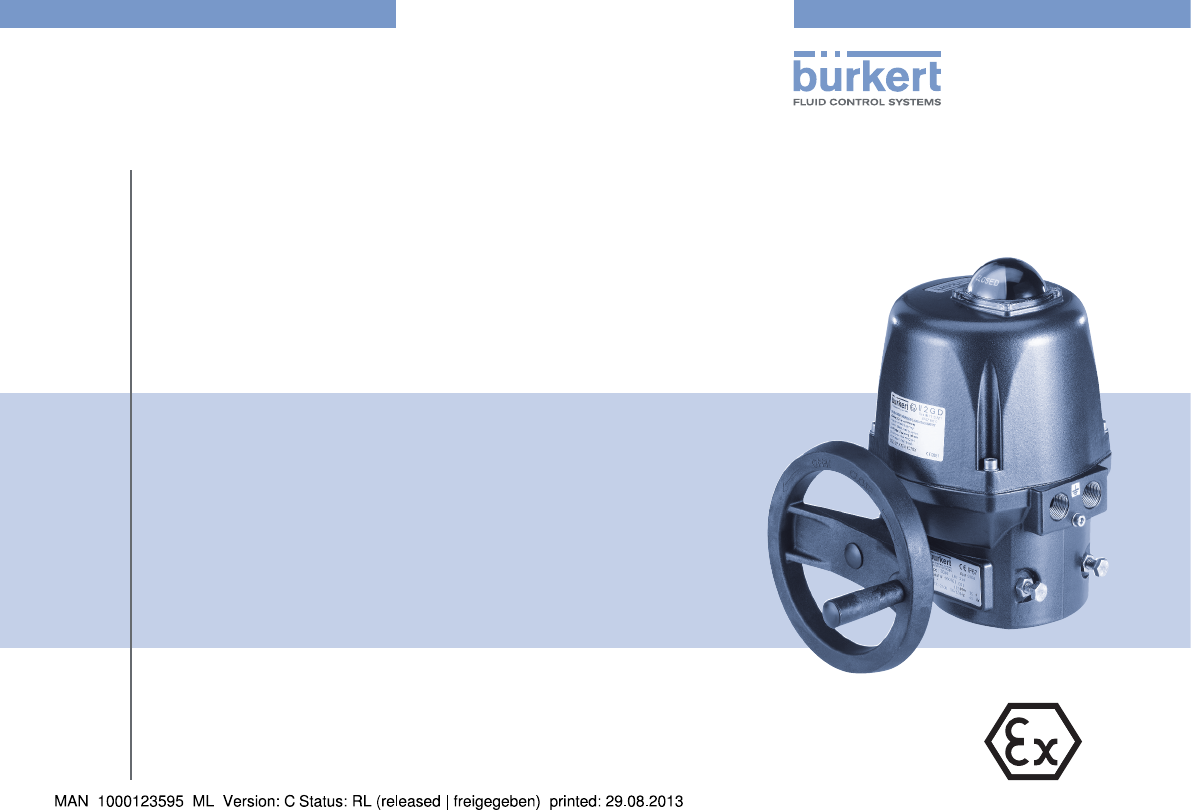
QuickstartType 3004LCIE 07 ATEX 6078 X Electric rotary actuator type 3004Elektrischer Drehantrieb Typ 3004Actionneur électrique type 3004Device with
10Installation7. INSTALLATION7.1. Safety instructionsDANGER!Risk of electric shock!There is a serious risk of injury when reaching into the device.•
11InstallationProcedure:Fig. 6: Standard installation → Ensure that the ball valve / the flap valve is in its closed position. → Carefully connect th
12InstallationAdjusting cams for limit switch contactsCamKeyAdjustment travelCamAdjustment travelKeyFig. 10: Adjusting limit switch clockwiseFig. 11:
13InstallationCheck on the rating plate of the rotary actuator whether the indicated voltage corresponds with the mains voltage.Cables with a diameter
14InstallationHAC B CEFDFig. 13: Power supply circuit board for actuators with 300 NmNo. Designations No. DesignationsAScrew for earthingELED 2: Erro
15InstallationOperating principle for Open / Closed mode (“Fig. 15”) • Switch open = actuator closes• Switch closed = actuator opensConnecting feedb
16InstallationProcedure: → Loosen left cable gland (pos.15, “Fig. 1” and “Fig. 2”) and feed through the cable to be connected. → Connect cable accordi
17Installation8.3.1. Specify the position of the plug-in jumpersON (turned on)OFF (turned off)Fig. 19: Plug-in jumper K1 / K2Fig. 20: Plug-in jump
18InstallationSpecify control signal typeControl signal when voltage 0 – 10 VR → Press <MEM> push-button and switch on the card (hold down push-
19Start-UpSpecify end positionsG → Press <MEM> and <OPEN> push-button to save the open position.The GREEN LED lights up 2x.All positions a
We reserve the right to make technical changes without notice.Technische Änderungen vorbehalten.Sous resérve de modification techniques.© 2009 - 2012
20Maintenance, Malfunctions10. MAINTENANCE, MALFUNCTIONSThe rotary actuator is maintenance-free when operated according to the instructions indicated
21 Inhalt:12. DER QUICKSTART ...2212.1. Darstellungsmittel ...
22Der Quickstart12. DER QUICKSTARTDer Quickstart beschreibt den gesamten Lebenszyklus des Gerätes. Bewahren Sie diese Anleitung so auf, dass sie für
23Bestimmungsgemäße Verwendung13. BESTIMMUNGSGEMÄSSE VERWENDUNGBei nicht bestimmungsgemäßem Einsatz des explosionsge-schützten elektrischen Dreh
24Allgemeine HinweiseExplosionsgefahr!Bei bestimmten Geräteausführungen besteht bei Öffnung des Gerätes im explosionsgeschützten Bereich Explosio
25Systembeschreibung16. SYSTEMBESCHREIBUNG16.1. Vorgesehener EinsatzbereichDer explosionsgeschützte elektrische Drehantrieb Typ 3004 (im Fol-genden
26Technische DatenMotor 100 - 300 NmNr. Bezeichnung1 Stellungsanzeige2 Haube3 Edelstahl-Schrauben4 Motor5.a Steuerung und Stromver-sorgung Karte5.b St
27Technische DatenHINWEIS! • Die Wärmequellen vermeiden, die zur Überschreitung des zuläs-sigen Temperaturbereichs führen können.17.5. Kennzeichnung
28Montage18. MONTAGE18.1. SicherheitshinweiseGEFAHR!Gefahr durch elektrische Spannung!Bei Eingriffen in das Gerät besteht akute Verletzungsgefahr.•
29MontageWichtiger Hinweis für die dauerhafte Funktion:Drehantrieb nicht kopfüber aufbringen! Dabei kann das Medium aus der Armatur in den Antrieb gel
3 Contents:1. QUICKSTART ...41.1. Symbols ...
30MontageVorgehensweise: → Glashaube des Stellungsanzeigers 1 inklusiv den Dichtring durch Lösen der vier Befestigungsschrauben abnehmen und die Glas-
31Installation19. INSTALLATION19.1. SicherheitshinweiseWARNUNG!Gefahr durch unsachgemäße Installation!Unsachgemäße Installation kann zu Verletzungen
32Installation19.2.2. 100-240 V AC (100-350 V DC) oder 15-30 V AC (12-48 V DC) StandardausführungDie Betriebsspannung des Antriebs beträgt 15-30 V A
33InstallationDer Drehantrieb kann in zwei verschiedenen Modi angeschlossen und betrieben werden:1. Drei Punkt Modus2. Auf / Zu ModusN-Ph+12 3T/EBil
34Installation2 31FC2FC1FCFFC04-657=CCABDDT/ESpannungsversorgung und SteuerungRückmeldungMotorBild 16: Interne Verdrahtung AntriebÜber zwei Nocken (P
35InstallationVorgehensweise: → Linke Kabelverschraubung (Pos.15, „Bild 1“ und „Bild 2“) lösen und das anzuschließende Kabel hindurchführen. → Kabel e
36Installation19.3.1. Position der Steckbrücken festlegenON (eingeschaltet)OFF (ausgeschaltet)Bild 19: Steckbrücke K1 / K2Bild 20: Steckbrücke K3 O
37InstallationUmgekehrte DrehrichtungR → Taster <CLOSE> drücken und die Karte ein-schalten (dabei Taster gedrückt halten).Die ROTE LED leuchtet
38InstallationEndlagen festlegenR → Taster <MEM> und <CLOSE> drücken, um die geschlossene Position zu speichern.Die ROTE LED leuchtet 2x a
39Inbetriebnahme20. INBETRIEBNAHME20.1. SicherheitshinweiseWARNUNG!Gefahr durch unsachgemäßen Betrieb!Nicht sachgemäßer Betrieb kann zu Verletzungen
4Quickstart1. QUICKSTARTThe Quickstart describes the entire life cycle of the device. Keep these instructions in a location which is easily accessibl
40Wartung, FehlerbehebungStörung AbhilfeDer Drehantrieb ist in der Position ZU verklemmt → Stromzufuhr überprüfen → Die Anschlüsse nach dem mitgeliefe
41 table des matIeres23. QUICKSTART ...4223.1. Symbole ..
42Quickstart23. QUICKSTARTLes instructions de service décrivent le cycle de vie complet de l‘ap-pareil. Conservez ces instructions de sorte qu‘elles
43Utilisation conforme24. UTILISATION CONFORMEL‘utilisation non conforme de l‘actionneur électrique peut présenter des dangers pour les personnes, le
44Indications généralesRisque d’explosion dû à la charge électrostatique !Il y a risque d’explosion en cas de décharge soudaine d’appareils ou de pers
45Description du système27. DESCRIPTION DU SYSTÈME27.1. Utilisation prévueL’actionneur électrique du type 3004 (appelé ci-après actionneur) a été
46Caractéristiques techniquesMoteur 100 - 300 NmN° Désignation1 Indicateur de position2 Capot3 Vis en acier inoxydable4 Moteur5.a Commande et alimenta
47Caractéristiques techniquesREMARQUE ! • Évitez les sources de chaleur susceptibles d’entraîner un dépassement de la plage de température admissible
48Montage29. MONTAGE29.1. Consignes de sécuritéDANGER !Danger présenté par la tension électrique !Il y a risque important de blessures lors d‘interv
49MontageRemarque importante pour un fonctionnement durable: Ne montez pas l‘actionneur électrique la tête en bas!Le fluide pourrait parvenir dans l’a
5Correct use2. CORRECT USEIncorrect use of the electromotive rotary actuator can be dan-gerous to people, nearby equipment and the environment. • Th
50MontageProcédure à suivre : → Retirez le capot de verre de l‘indicateur de position 1, y compris la bague d‘étanchéité, en desserrant les quatre vis
51Installation30. INSTALLATION30.1. Consignes de sécuritéAVERTISSEMENT!Danger dû à un montage non conforme !Un montage non conforme peut entraîner d
52Installation30.2.2. Version standard 100-240 V AC (100-350 V DC) or 15-30 V AC (12-48 V DC)La tension d’alimentation de l’actionneur électrique e
53InstallationL‘actionneur électrique peut être raccordé et utilisé avec deux modes différents :1. Mode trois points modulants2. Mode ouvertur
54Installation2 31FC2FC1FCFFC04-657=CCABDDT/EAlimentation en tension et commandeRecopieMoteurFig. 16 : Câblage interne de l’actionneur électriqueLes
55InstallationProcédure à suivre : → Desserrez le presse-étoupe (pos.15, « Fig. 1 » et « Fig. 2 ») gauche et faites traverser le câble à raccorder. →
56Installation30.3.1. Déterminer la position des cavaliersON (activé)OFF (désactivé)Fig. 19 : Cavalier K1 / K2Fig. 20 : Cavalier K3 OFF Fig. 21 :
57InstallationSens de rotation inverseR → Appuyer sur le bouton-poussoir <CLOSE> et activer la carte (maintenir le bouton-poussoir enfoncé).La L
58InstallationDéterminer les positions finalesR → Appuyer sur le bouton-poussoir <CLOSE> pour amener la vanne en position ouverte.La LED ROUGE s
59Mise en service31. MISE EN SERVICE31.1. Consignes de sécuritéAVERTISSEMENT !Danger dû à une utilisation non conforme !Une utilisation non conforme
6General InformationDanger of explosion caused by electrostatic charge!If there is a sudden discharge from electrostatically charged devices or person
60Transport, Stockage, RECYCLAGEPanne RemèdeL'actionneur électrique est bloqué en position FERME → Vérifiez l'alimentation en courant. → Vér
www.burkert.com
7System Description5. SYSTEM DESCRIPTION5.1. Designated Application AreaThe explosion-protected electromotive rotary actuator Type 3004 (desig
8Technical dataMotor 100 - 300 NmNo. Designation1 Position indicator2 Hood3 Stainless steel screws4 Motor5.a Control and power supply card5.b Power su
9Technical dataNOTE! • Avoid heat sources which may result in the permitted tempera-ture range to be exceeded. 6.5. IdentificationThe rotary actuato
More documents for Accessories for water Burkert Type 3004

Related products and manuals for Accessories for water Burkert Type 3004


 (34 pages)
© 2020, manymanuals.com. All rights reserved. | 2.646 s |
 Manymanuals.com
 Manymanuals.de
 Manymanuals.fr
 Manymanuals.it
 Manymanuals.pl
 Manymanuals.cz
 Manymanuals.es
 Manymanuals-pt.com
Comments to this Manuals